
Router Circle Jig – Festool OF1400 or other Template Guide Router
By mgrobins
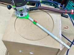
Adjustable Jig for creating circular cuts with a router – perfect for round holes or round objects and arcs.
Designed for the Festool OF1400 Router or any router which will fit a 30mm Template Guide Bushing (an insert for smaller guides is easily done if you need one for your router.
Festool only include a 30mm Template Guide Bushing thus the chosen dimension for this jig.
The Guide bushing fits snug into the centre of the jig allowing a precise measured radius, stable router and yet you may rotate the router on the circle jig so you can keep 2 hands on it and prevent dust hose or cable entanglement.
Most jigs require you to bolt your router to the jig – a slow and cumbersome process.
My design takes only seconds to use. Snap or screw on the bushing and sit the router on the jig.
DETAILS:
Jig Components and use:
-
Main body. This is sized for the OF1400 and should be plenty large enough for other routers. Its thickness is designed so guide bushing does not protrude onto work piece.
-
Square tube of 20mm /side. Aluminium is ok as long as it’s rigid for the length of cuts you want to make. For long bench arcs etc thick wall tube or steel may be better to stop flex. For speaker cutouts or whatnot… Aluminium basic tube is just fine.
-
Sliding centre pin. A block that slides along the main shaft and has a metal pin of 5mm diameter protruding which acts as the centre pivot when cutting circles. Two small m5 bolts or screws will secure this to the rail and prevent drift in the setting while under tension routing. If you use a different radius pin – just account for that in your calculations!
- Radius insert. Fits into the main body and enables a ruler to be used to accurately measure from centre pin to centre of router bit.
This measurement and precise knowledge of the pin/bit diameter is essential to achieving perfect accuracy.
The insert allows a tape measure to hook on, or a sliding angle rule to butt against it for precision.
PRINTING:
0.3mm PLA+ is just fine.
Use supports – the 3mf has snug supports to minimise their size.
The accuracy of your printer may influence the fit of the Guide Bushing – if it’s too tight use fine sand paper to relieve the centre of the jig until it fits and rotates smoothly. Some wax is helpful too.
Printed parts:
Main body, Sliding pin holder, Radius setting Insert, A nail holder for scoring the radius for visual check if you want to. Low profile “Star” knobs to glue on hex bolts to ease use of the jig.
Bill Of Materials:
-
20mm square tube of length desired; Use steel for rigidity if doing really long arcs for benchtops etc. Too long is a PITA when completing full circles so I urge restraint :P.
-
Short M5 bolts x2 (10mm) and Hex nuts x2 for securing the adjustable centre pin holder. Too long and they will catch on your dust collection – about 9mm seems good.
- A 5mm (or other size) “Pin” – An M5 hex Cap bolt with part smooth shank cut to length works well glued into sliding holder. Too thin a pin can be a problem in soft material because it can cut into it and become loose, or bend.
This can be a hex bolt or fine threaded bolt also – just make sure it’s accurately dimensioned because you will use it in your measurements!
I used a long hex cap screw and cut the threaded part off leaving the smooth shank.
I used a heatgun, on the holder because pin was quite long and making the holder bendy for a few moments got it in.
**When you glue the pin place the holder with the pin in a perpendicular hole. This is important for smooth function and the holder moving under tension when cutting.
-
Four screws to secure the main body to the tubing. I used self-cutting flat head metal screws. The bottom ones must NOT protrude else they will interfere with rotation of the jig.
<13mm length is good.
You may also glue the tube to the main body… no screws needed! - Epoxy: this is advised for securing the pin and the knobs.
NOTES on Calculating your cut dimension:
When you cut out a circle on paper the circle and hole appear to match in size. With a router this will not be so. The thickness of the router blade will be removed from the material… thus it MUST be accounted for to ensure you have a correct hole or correct circle cutout.
For practicality, account for the dimension of centre pin and bit to have a consistent system for measuring. It is HORRIBLE when you cut and find your hole is too big because you added where you should have subtracted…. I find it best to draw so I can see each dimension and visualise what I am doing. This may help you too.
Example: I want a 40cm diameter circular hole. My centre pin is 5mm and my router bit is 13mm.
With a desired cutout radius of 20cm, I need to compensate now for the thickness of the pin and cutting bit. I place the “Radius Insert” in. I can measure from the outside of the pin or its inside with reference to the insert and this will determine if I add or subtract the pins radius. I prefer to use the outside of the pin so my sliding square can butt against it.
Let’s visualise what’s going on (you don’t need to accurately draw)…
I draw a line – my 200mm radius.
My pin centred on the start is 5mm wide (which I draw)… so is an extra 2.5mm I must account for as a + or – depending in which side I measure from.
My router bit is 13mm and if centre on the end of the 200mm radius… the cut will be 206.5mm so I need to slide it 6.5mm in. “-6.5mm” to ensure the cut is inside the desired radius. If I were wanting to keep a 200cm circular plate… I would slide it 6.5mm out.
This equates to a jig setting of 200mm +2.5mm-6.5mm = 196mm.
I adjust the jig so outside centre pin to insert is 196mm.
Being fixed I can now take multiple passes until I reach my desired depth of cut.
BUT WHAT ABOUT THE CIRCLE I CUT OUT?
if I were to measure it, the diameter would be 26mm less than the hole created…because unlike a knife cutting along a line the router removed the thickness of the bit around the entire circumference (thus 2x diameter of bit).
**If you are cutting through material (resting on a sacrificial board or not), leave some small “tabs” in 3-4 locations spaced around when you are at your final depth of cut and “through”. This prevents the centre mass and jig with dangerously fast router falling into your box OR the centre part moving and the router hitting the wrong spot, damaging all of your fine effort or taking off a finger.
Once done, use a small hand saw or knife to cut the tabs and the centre will come free.
May 22, 2024 at 05:19AM
via Thingiverse – Newest Things https://ift.tt/LWU1uS4

Lascia un commento